
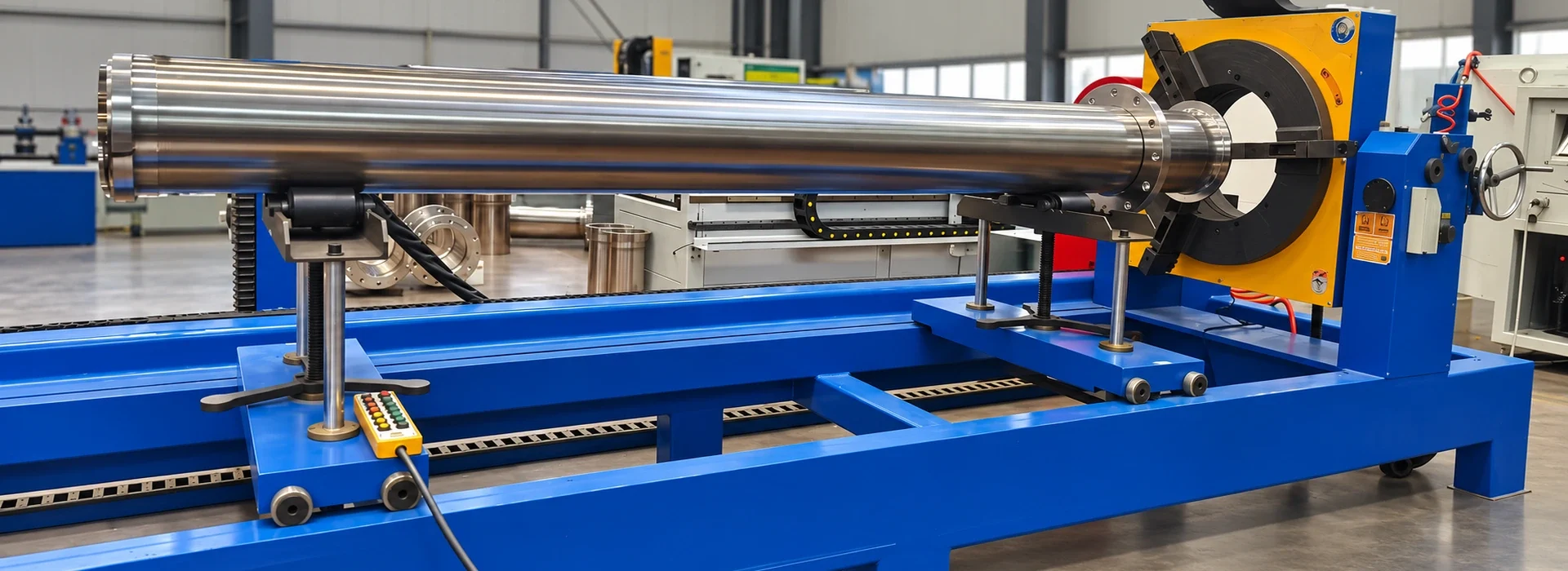
Pipe-to-flange welding is a repetitive yet quality-critical operation in industrial pipe fabrication. For manufacturers producing pipe assemblies, pressure vessels, process piping, and industrial fittings, automated pipe-to-flange welding can improve weld consistency, production throughput, and process control.
Could rotating the workpiece—rather than the torch—make pipe-to-flange welding simpler?
1. How a Rotary Pipe Welding System Works
In conventional orbital welding, a welding head travels around a stationary pipe. In a rotary pipe welding system, the workpiece is driven by a motorized positioner while an automatic welding torch remains at a controlled location.
MecaNext rotary welding solutions combine programmable workpiece rotation with adjustable torch positioning. Depending on workpiece geometry, access, and fixture design, the torch may be configured to reach external fillet welds, internal fillet welds, or circumferential butt joints.
How the Rotary Welding Process Works
A rotary pipe-to-flange welding system controls the movement of the workpiece and the welding torch as one coordinated process.The pipe and flange assembly is secured in a dedicated fixture, while a motorized positioner rotates the workpiece at a controlled speed.
The welding torch remains positioned at the selected joint location. This arrangement helps maintain a consistent torch angle, arc length, travel speed, and heat input throughout the circumferential weld.
Typical Operating Sequence
Load and fixture the assembly
The pipe and flange are aligned and secured in a dedicated fixture.Set the welding parameters
The operator selects rotational speed, welding current, travel speed, shielding gas flow, and torch position.Position the torch
The torch is adjusted for an external fillet weld, internal fillet weld, or circumferential butt weld.Start the automated welding cycle
The positioner rotates the workpiece while the torch follows the programmed welding path.Complete inspection and unloading
After welding, the operator checks the weld profile and removes the finished assembly.
Why Rotate the Workpiece?
This approach is especially suitable for repetitive pipe-to-flange welding applications where the pipe diameter, flange dimensions, and joint geometry remain consistent from one assembly to the next.Rotating the workpiece can simplify repetitive circular welding because the torch remains in a stable and accessible position. Compared with manually moving a torch around a stationary assembly, this approach may help improve:
- Weld bead consistency
- Torch accessibility
- Parameter repeatability
- Operator ergonomics
- Production cycle control
- Fixture-based repeat production
The final machine configuration depends on pipe diameter, flange dimensions, wall thickness, material, joint design, required weld position, and production volume. A sample weld test using the actual workpiece is recommended before final equipment selection.
Rotating workpiece + controlled torch position + repeatable welding parameters = a streamlined automation approach for suitable circular welds.
REAL EQUIPMENT IMAGES
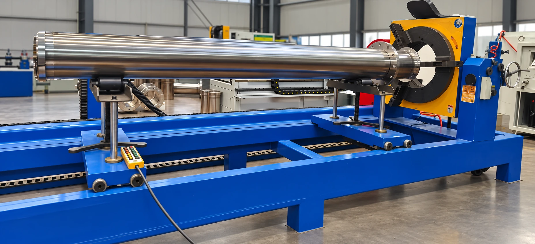
Rotary pipe welding platform with a motorized positioner for circumferential welding production.
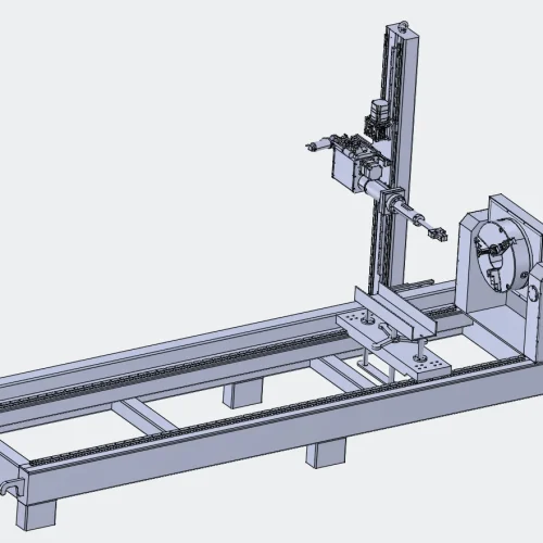
Engineering drawing of the rotary welding system structure, showing the torch support and positioner layout.
- Controlled rotation: Repeatable rotational speed for consistent circumferential travel.
- Adjustable torch: Torch position and angle tailored to the weld location.
- Process integration: TIG/GTAW or MIG/MAG/GMAW based on joint needs.
- Production repeatability: Reduced dependence on manual torch movement.
2. Automatic Fillet Welding for Slip-On and Socket-Weld Flanges
Fillet welds are common in pipe-to-flange fabrication, but the joint location varies with flange type. A slip-on flange typically requires an external and an internal circumferential fillet weld. A socket-weld flange normally uses an external fillet weld at the hub.
Access to recessed or differently oriented joints may be difficult for some conventional orbital heads. With a rotary system, the torch is positioned at the required joint location and the fixture rotates the assembly through the programmed welding cycle.
Where geometry and clearance permit, the same platform can be adapted to multiple fillet-weld arrangements. The choice of torch, fixture, and welding procedure still needs to be validated for each component design.
FILLET WELDING EXAMPLES
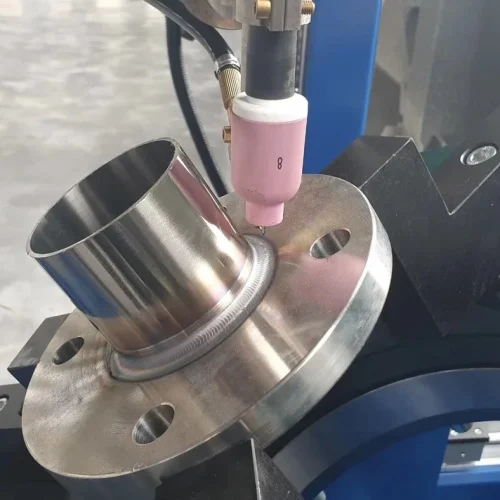
External circumferential fillet welding with controlled torch positioning.
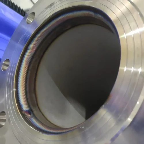
Internal fillet weld close-up showing the weld path around the flange bore.
3. Automatic Butt Welding for Weld-Neck Flanges
Weld-neck flanges are generally connected to pipe through circumferential butt welds. These joints are used in piping applications where weld integrity is particularly important, and inspection requirements can include radiographic testing (RT) or other nondestructive examination when specified.
For suitable joint preparations and wall thicknesses, a rotary system configured for automatic TIG butt welding can support controlled root, fill, and cap passes. Programmable torch oscillation and adjustable sidewall dwell settings can help manage bead placement and sidewall fusion during multi-pass welding.
Controlled parameter repeatability can support the use of qualified welding procedures for projects operating under applicable ASME codes and standards or EN/ISO requirements. It does not itself certify a weld: acceptance depends on the qualified procedure, base material, joint preparation, actual welding conditions, and inspection criteria.
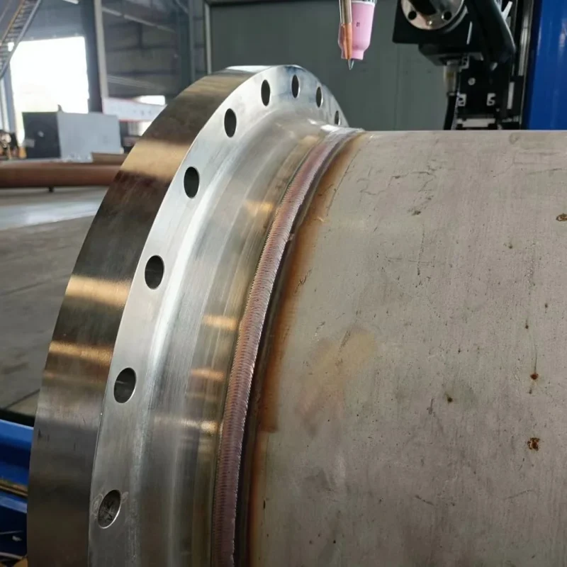
Close-up of an automatic circumferential butt weld joining a pipe to a weld-neck flange.
4. Higher Throughput with Multi-Torch Configurations
When pipe-to-flange welding assemblies are produced in volume, reducing the number of sequential welding operations can increase output. MecaNext can engineer single-torch, dual-torch, and four-torch configurations for suitable component designs.
Potential applications include simultaneous internal and external flange fillet welding or welding at both ends of a pipe assembly. A multi-torch arrangement may shorten the welding portion of the cycle, though overall throughput also depends on loading, unloading, fit-up, fixturing, and process limitations.
These systems are most attractive when joint geometries are repeatable, production quantities justify dedicated tooling, and torch clearance permits simultaneous operations.
APPLICATION DETAILS
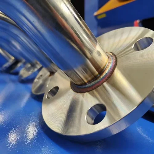
Pipe-to-flange welding application with controlled torch positioning.
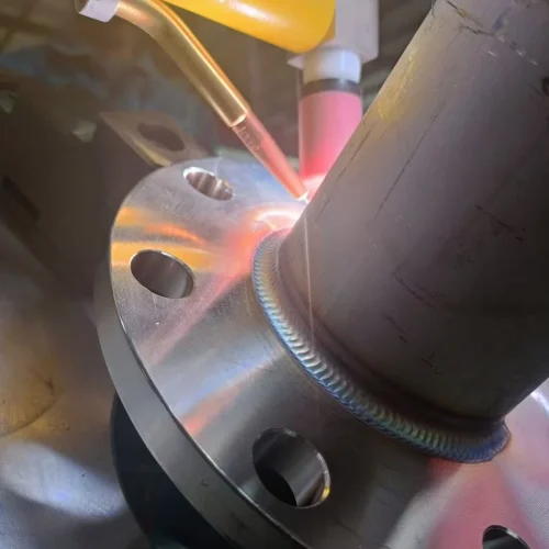
Pipe-to-flange butt weld close-up showing the finished weld profile.
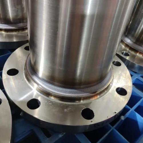
Internal fillet weld close-up showing the weld path around the flange bore.
5. TIG vs. MIG/MAG: Which Process Fits the Application?
There is no universally best process for every pipe flange welding machine. The appropriate choice depends on material, wall thickness, joint design, deposition requirements, and applicable inspection specifications.
| Factor | TIG / GTAW | MIG/MAG / GMAW |
|---|---|---|
| Typical priority | Precise heat and bead control | Higher deposition and production output |
| Common fit | Stainless steel and quality-sensitive joints | Suitable carbon and low-alloy steel applications |
| Key consideration | Travel speed and multi-pass cycle time | Joint access, shielding, and process qualification |
6. When Is Rotary Welding the Right Choice?
Rotary workpiece welding is particularly suitable for repeatable circular joints with consistent geometry and secure fixturing. Conventional orbital welding remains highly effective for many fixed-pipe butt welds, while robotic systems offer flexibility for complex, non-circular paths.
Before choosing an automation platform, assess pipe diameter and wall thickness, flange type, material, welding position, torch access, required production volume, joint preparation, and inspection expectations. A trial weld using the actual parts is often the most useful way to validate the approach.
For repetitive pipe-to-flange welding involving fillet and butt joints, rotary welding may offer a simpler and potentially more economical alternative to a general-purpose robotic cell.
Frequently Asked Questions About Pipe-to-Flange Welding
What is pipe-to-flange welding?
Pipe-to-flange welding is the process of joining a pipe to a flange using a fillet or butt weld. The flange provides a connection point for pipes, valves, vessels, or other industrial components. The process can be performed manually or with an automated rotary welding system.
Can pipe-to-flange welding be automated?
Yes. Pipe-to-flange welding can be automated when the pipe diameter, flange geometry, material, joint design, and production requirements are sufficiently consistent. A rotary welding system can rotate the workpiece at a controlled speed while the torch maintains a stable welding position.
What type of welding system is suitable for flange fillet welds?
A rotary pipe-to-flange welding system is often suitable for repetitive flange fillet welds. The correct system depends on pipe diameter, flange size, wall thickness, material, weld position, torch access, and required production volume. A sample weld evaluation is recommended before selecting equipment.
When should a rotary welding system be used instead of a robot?
A rotary welding system is usually suitable for repeatable circular welds with consistent dimensions and fixed workholding. A multi-axis robot is more appropriate when the production line must handle complex paths, changing geometries, multiple welding positions, or a wide range of part sizes.
What information is needed to select a pipe-to-flange welding machine?
The equipment supplier normally needs the pipe outside diameter, wall thickness, flange dimensions, material, joint type, welding process, production volume, shielding gas, and inspection requirements. Weld drawings, sample parts, and photos can also help engineers recommend the correct system.
Need to Automate Pipe-to-Flange Welding?
Send us your pipe diameter, wall thickness, flange type, material, and production requirements. The MecaNext engineering team can recommend a suitable rotary welding system for your application.